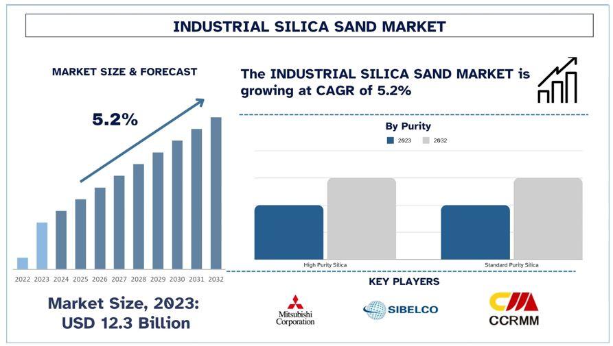
Industrial Silica Sand Market Analysis by Size, Share, Growth, Trends and Forecast (2024–2032) | UnivDatos
Other |
2024-12-06 07:07:33

Among the most important aspects of this document are the determination of the pouring position, the parting surface, and the parameters of the die-casting process. The die-casting process drawing is a technical document that is used to guide the process of die-casting zinc alloy. Its purpose is to provide direction for the process. In addition to serving as the primary foundation for the acceptance of zinc alloy die-casting components, the die-casting process drawing also serves as these components' primary foundation. A determination is made regarding the location of the pouring position during this stage.
In the industry, this particular position is known as the pouring position. One of the most important factors that determines the quality of the casting, as well as the dimensional accuracy of the molding process and the level of difficulty of the process, is the position at which the casting is poured. Every one of these elements is connected to the others. In the course of the pouring process, the gas, the slag in the molten metal, and the sand in the mold will all float, which may result in flaws in the upper portion of the casting. The presence of pores, slag inclusions, and blisters are all examples of these defects.
On the other hand, the lower portion of the casting has a denser structure and is less likely to have defects than the upper portion of the casting. This is because the lower portion's structure is more compact. The execution of this action cable clamp connector is carried out in order to ensure that the quality of this essential working surface is maintained. Through the use of the illustration, it is made abundantly clear that the requirements for the quality of the circumferential surface of the winch are relatively high.
At the second stage, the large flat surface of the casting is poured in a direction that is either tilted or below the horizontal. This is done in order to create the desired shape. The pouring process causes a significant amount of heat to be released into the upper portion of the mold as a result of the hot, molten metal that is being poured. Because of this, the top surface of the molding sand will expand, arch, or even crack, which will result in defects such as sand inclusions and blisters appearing on the large surface. This will be a consequence of the circumstances described above. Both of these choices are excellent choices to consider. The two choices presented here are both recommended. You should make it easier to position risers in dense areas specifically for the purpose of feeding and feeding them. First and foremost, this is the objective of this project. The selection of the surface is significant for the purpose of partitioning.
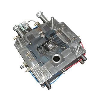
The joint surface that is present between the components of the mold is one of the surfaces that is referred to as the parting surface. This surface is also known as the joint surface. It is essential to adhere to the principles that are described in the following paragraphs in order to gain an understanding of the surface of the parting.
When choosing the parting surface, it is recommended that it be chosen at the point where the cross-section of the pattern is the largest. The decision to go with this preference was made with the goal of simplifying the process of mold removal. When it comes to machine modeling, there is typically only one parting surface present the vast majority of the time. It is reasonable to have two parting surfaces when it comes to the production of single pieces and when it comes to manual molding. This occurs as a result of the characteristics of the manufacturing process. This action is taken in order to reduce the amount of tooling that is produced, which is the primary goal of this action.
The fourth step is to make an effort to save as many of the castings as you can within the same sand box. This is the fourth step.
The fifth step is to make an effort to keep the core in the lower box, and to pay close attention to making sure that the height of the sand box is as low as it can possibly be. Molding can be simplified as a result of this, core setting and molding can be made simpler, and mold removal and molding can be made simpler. All of these benefits casting services can be realized. Each and every one of these things can be simplified. The casting material, the casting method, the production batch, the casting size, the pouring position, and other factors are included in this category of considerations.
Following the determination of the tolerance level and the machining allowance level of the casting, the value of the machining allowance can be chosen in accordance with GB/T11350-1989, and the value of the tolerance can be chosen in accordance with GB6414-86. Both of these choices are possible. Both of these options are open to consideration. It would be possible to carry out the casting process in a more effective manner as a result of this.
The extent of the draught's angle
The Direction of the DraftWhen we talk about the draft angle, we are referring to the slope of the wall on the pattern that is parallel to the direction in which the draft is moving. This particular angle can be expressed in two different ways, depending on the context, either as the width a or as the angle α. The utilization of width a is something that you should give serious consideration to. It is possible to implement each and every one of these various kinds of strategies. The JB/T5105-1991 standard can be utilized in order to determine the draft angle when clay sand modeling is utilized. This can be accomplished by applying the standard. The slope of molds that are typically made of wood can range anywhere from 0.6 to 3.0 millimeters, whereas the slope of molds that are made of metal can range anywhere from 0.4 to 2 millimeters. When the ratio of the height to the diameter of the hole in the casting is less than one (H/D is less than 1), it is possible to cast the hole using a core that is enclosed within itself. This is in contrast to the situation in which the ratio is greater than one. In circumstances in which the distance between the two dimensions is less than one, this is the situation that occurs.
The rate at which the object is decreasing in size
The size of the pattern needs to be increased in order to make the cooled casting conform to the specifications of the drawing and to compensate for the shrinkage of the casting that occurs during the cooling process. This is necessary in order to achieve the desired results. It is possible to reduce or eliminate the risk of causing damage to the sharp corners of the mold by casting the sand mold with round corners. This is in contrast to the traditional method of casting the mold. It is also possible that this will prevent cracks from appearing, cavities caused by shrinkage, and sand from adhering to the surface. In contrast, the corners of the casting parting surface must not have any rounded corners at any point in time, under any circumstances. This is a requirement that must be met. The cavity in the mold that is specifically designated for the placement of the core head is referred to as the core seat. The mold contains this cavity in its structure.